Supplement 2.17: The Microwave Radiometer (2/2)
Oil detection
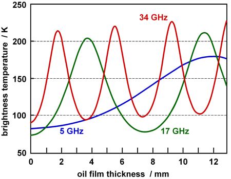
We have seen that the oil film thickness on water must be in the millimetre to centimetre range, to give rise to interference fringes in the microwave spectral range. This is depicted in the graph below.

Source: The Archimedes 1 Experiment, Joint Research Centre, Ispra Establish- ment, redrawn.
The fringes should make it possible to measure the thickness of oil layers on the water surface with a MWR Scanner! The signal at a given frequency is modulated during overflight of an oil spill, depending on the local layer thickness. Measured intensities are then converted to brightness temperature variations using Planck’s Radiation Law. But a single detection frequency will lead to ambiguous data due to the periodic variations of the brightness temperature with increasing or decreasing oil layer thickness. This, however, can be overcome with instruments that use several frequencies, as shown in the graph above.
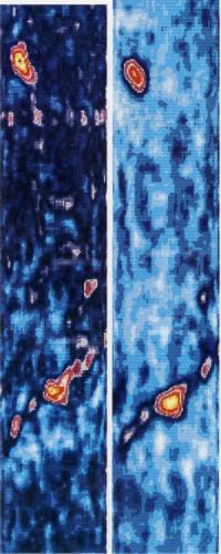
The capabilities of measuring oil layer thickness with MWR are clearly seen in the data of two radiometers having 90 and 32 GHz detection frequency. We know that large volumes of oil discharged on water are characterised by a core having a layer thickness in the order of millimetres to centimetres, surrounded by thin layers of oil only a few micrometres thick which are disrupted by the wind into small patches. Obviously, the MWR Scanner does not “see” these thin films. It locates the thick portions of an oil slick, which makes it suitable for guiding recovery vessels during oil spill clean-up operations.
Serious limitations of MWR applications arise when trying to detect weathered oil volumes. Due to wind and waves, water droplets are constantly dispersed into an oil layer, leading to emulsification. The principle of microwave radiometry is the detection of thermal radiation emitted by the water below the oil. This radiation is transmitted through the transparent oil layer (and hereby modulated by interference). Water droplets in oil however emit thermal radiation in the same way as a clean water surface. Due to this, emulsified oils are invisible to microwave radiometry.
Another limitation occurs in cases where the oil layer thickness varies to strongly over short distances which cannot be resolved with the pixel distribution of the MWR Scanner on the ground. As a consequence one ore more minima or maxima of the interference fringes are not detected, and hence not counted when evaluating the oil layer thickness. This can lead to incorrect results of the oil layer thickness distribution derived with MWR Scanners.

Source: The Archimedes 2 Experiment, Joint Research Centre, Ispra Establishment.
Related SEOS links
- Worksheet: Interference Fringes of Oil on Water,
as html page or as printable rtf file - Visual Inspection of Oil Spills
- The Side-looking Airborne Radar (SLAR)
- The UV-IR Scanner
- The Laser Fluorosensor (LFS)
