Supplement 1.13: Semiconductor photodiodes (4/4)
Electronic circuitry
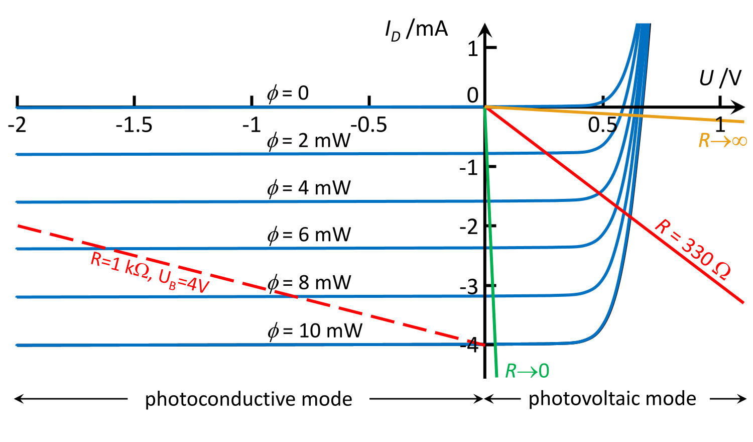
The possibilities offered by electronic circuitry become clear when the characteristic curve of a photodiode is supplemented with resistance lines.
The following diagram of the basic circuit configurations illustrates the different operating modes.

Ways of connecting a photodiode.
Version a) requires no external operating voltage. The photodiode is used in photovoltaic mode. It acts as a current source whose output depends on the level of illumination. The photocurrent generates a voltage across the resistor . This corresponds to the red resistance line in the characteristic curve diagram, which starts at the origin, with . Instead of an ohmic resistor, another electrical load may also be used. Solar cells operate according to this principle, with the load line shaped in such a way as to achieve the maximum possible electrical power .
The red resistance line shows that the linearity of the output signal is lost as illumination increases, when the diode’s forward current is added to the photocurrent. This is even more pronounced for very high resistance values or very low diode currents. The yellow resistance line illustrates this for ; it lies almost on the voltage axis in the forward region. If we set in the Shockley equation for photodiodes
and take the logarithm of the equation, the following results:
The voltage across the diode is proportional to the logarithm of the photocurrent and thus to the brightness. The resistor can be omitted and the diode connected directly to a high-impedance voltmeter (multimeter, oscilloscope). As the reverse current is highly temperature-dependent, the circuit is not particularly suitable for logarithmic measurements of brightness.
Version b) uses an external positive operating voltage at the cathode. This corresponds to the red dotted resistance line in the characteristic curve diagram, with and . In darkness, ; the photodiode is then subjected to a reverse voltage of almost the full operating voltage. The limitation arises from the reverse current , which produces a disruptive and temperature-dependent baseline value when measuring weak light signals. Increasing illumination results in a voltage proportional to the brightness.
As shown on page 2, the capacitance of a pin photodiode with an external reverse voltage is small; the circuit is therefore suitable for measuring high light frequencies and short light pulses.
Version c) aims to measure the photocurrent directly using a current measuring device with as low a resistance as possible. This operating mode corresponds to the green straight line labelled in the characteristic curve diagram. Due to the higher capacitance of the diode without reverse voltage, the circuit is not suitable for measuring fast signals. However, a major advantage is that the operating point lies at the origin in the dark, as no reverse current occurs here. This allows very small signals to be measured with high sensitivity. The only source of interference is the photodiode’s noise.

The diagram on the right shows an operational amplifier (op-amp) used to amplify the photocurrent from a photodiode. This circuit is known as a photodiode amplifier.
The function of the operational amplifier is to minimise the voltage difference between its inverting (-) and non-inverting (+) inputs. It therefore regulates the potential at the inverting input to zero. To achieve this, it generates an output voltage Ua which causes a current to flow through the resistor R in such a way that the sum of the currents at the inverting input is zero (Kirchhoff’s node rule). The current through R is therefore equal to -Iphoto. The reverse voltage across the photodiode does not change; this is an advantage of the circuit compared with using a resistive resistor alone. Because the inverting input is used, the output voltage has the opposite sign to that of the simpler circuit shown above, which does not use an op-amp.
To reverse the polarity of , the photodiode can be connected in reverse to the inverting input of the op-amp. In this case, the polarity of the external voltage across the photodiode must also be reversed. This also applies in the same way to the simpler circuit shown in the left-hand column. The bias voltage of the photodiode can also be zero, which, in turn, allows measurements of low brightness levels due to the absence of reverse current in the diode, provided the op-amp is a low-noise type.
Bibliography
A recent and detailed overview of the physics and state of the art in photodiodes can be found in
- Vasco D. B. Bonifácio & Rita F. Pires: Photodiodes: Principles and recent advances, Journals of Materials NanoScience, 6(2), 38-46, 2019.
As with vacuum photodiodes and photomultipliers, there are also informative company publications on semiconductor photodiodes. These include
- several publications by OSI Optoelectronics on photodiodes, last access: 24.06.2026
- Hamamatsu Si photodiodes, last access: 24.06.2026
- Vishay Semiconductors: https://www.vishay.com/docs/80086/physicstechnology.pdf, last access: 24.06.2026.