Supplement 1.12: Photomultipliers (2/3)
Spectral sensitivity
There is a wide range of spectral sensitivities for photocathodes. The properties described for vacuum photodiodes apply here in the same way. The following figure shows some commonly used sensitivities.
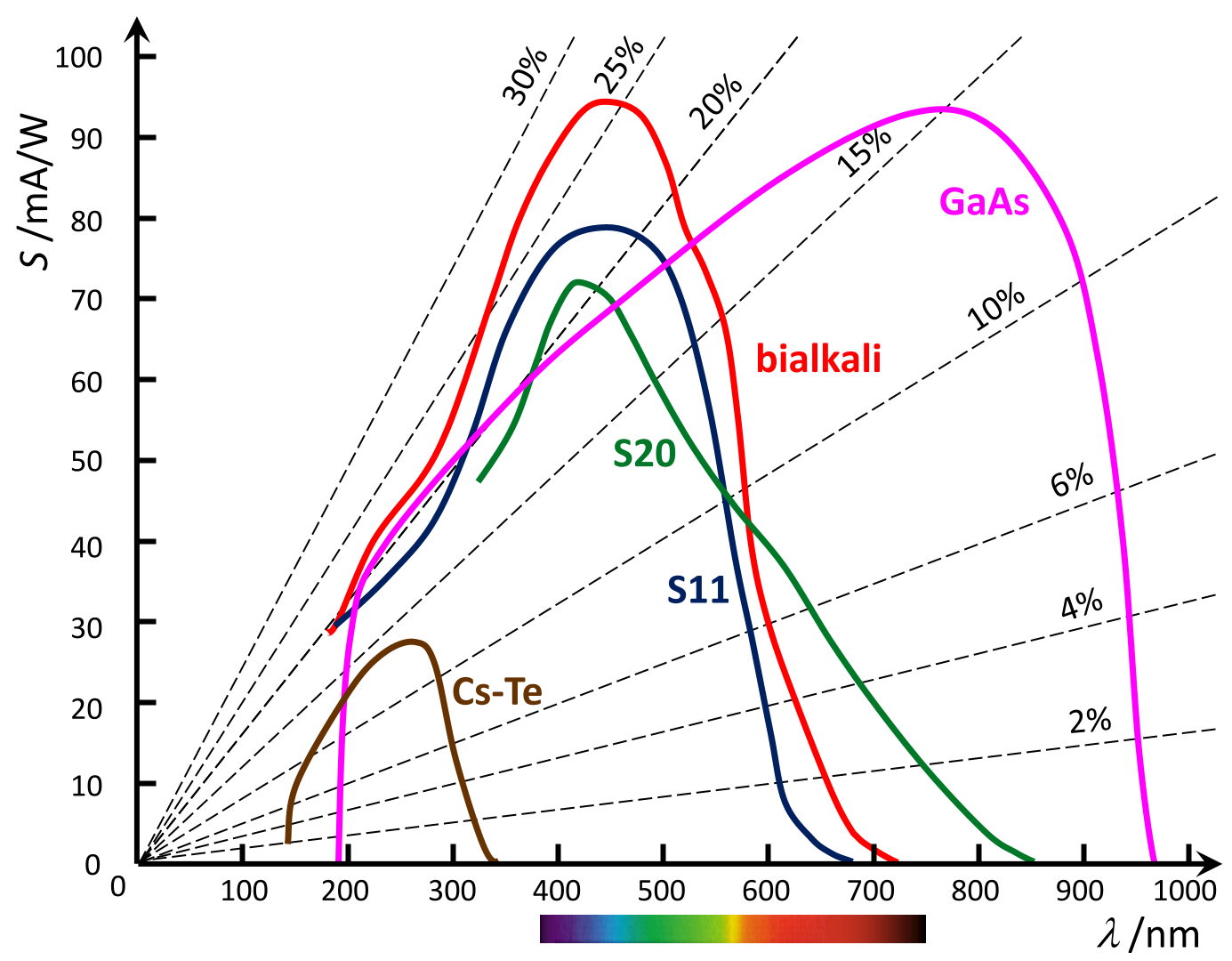
It would be a mistake to assume that a cathode with the broadest possible spectral response, such as that of the GaAs cathode, is always the best choice. Rather, the nature of the application is decisive. If, for example, only ultraviolet radiation is to be measured even in daylight, the Cs-Te cathode, one of the so-called solar blind types, is preferable. This is helpful because most optical coloured glass filters allow long wavelengths to pass through (long wave pass), and the few available short wave pass filters do not have sharp absorption edges. Even interference filters do not always block regions outside their transmission wavelength sufficiently efficiently. Therefore, a photomultiplier with a suitable filter function in the cathode is often the first choice when stray light needs to be suppressed. For example, the S11 cathode is sensitive from UV to yellow/orange and suppresses light from deep red onwards very effectively.
The broadband GaAs cathode is advantageous when measurements need to be taken from the UV range into the near-infrared; however, this material is easily overloaded at high brightness levels and can suffer permanent damage; this effect is reversible after a few days, but not always.
Time behaviour
The time response of photomultipliers is roughly equivalent to that of vacuum photodiodes. This also applies to the parasitic capacitances, which is why low anode resistance values of typically 50 Ω are required for high-frequency measurements. This is not a significant difficulty, as the amplification provided by the dynodes yields high output signals compared to photodiodes. However, the transit time of the electrons from the photocathode via the dynodes to the anode must also be taken into account. This decreases with increasing dynode voltages and is typically around 20 ns, depending on the number of dynodes. A key factor in the time response is the variability of the transit time along different paths from the cathode to the anode, which broadens pulsed signals and reduces the cut-off frequencies. With the aim of achieving transit times that are as identical as possible, multipliers with optimised dynode shapes, known as compensated-design multipliers, have been developed.
Design types
As shown in a photograph on the previous page, the size of photomultipliers can vary considerably; this is always tailored to the specific application. The design is equally important. A key difference is the orientation of the photocathode relative to the longitudinal axis of the tube. The side-on orientation is implemented in the example of the 1P28 type shown below. In this case, the photocathode is opaque, and the photoelectrons are emitted from the side of the photocathode facing the incident light. In the head-on design, the photocathode consists of a thin layer vapour-deposited onto the inner surface of the flat light-entry window. In this case, the cathode is semi-transparent, so that the photoelectrons are emitted backwards towards the dynodes. However, this reduces the quantum yield compared to the side-on variant.
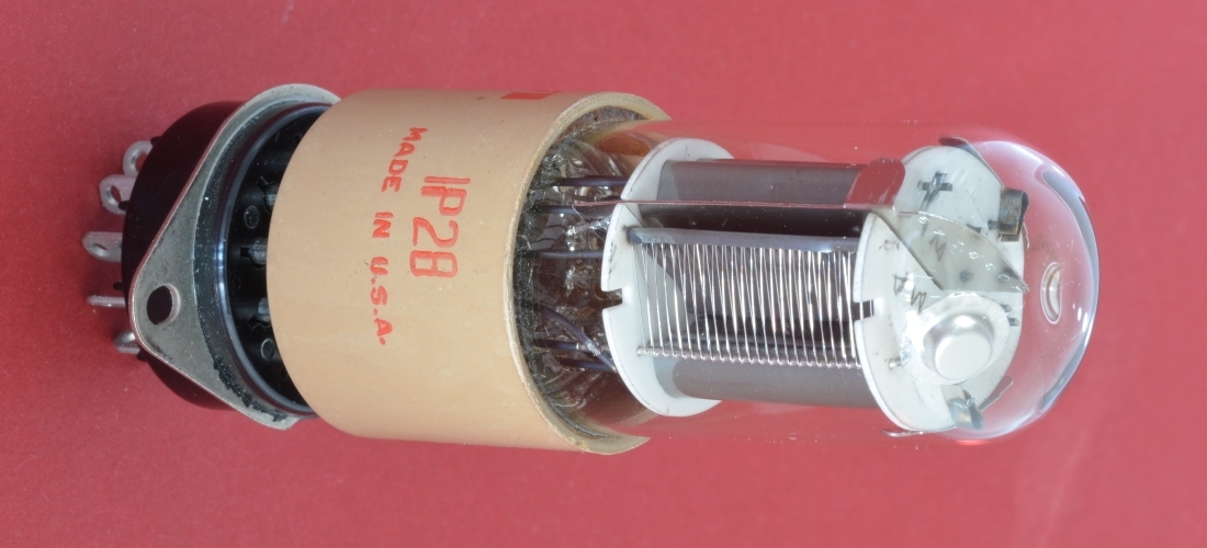
Left: View of the cathode side. The wires form a grid-shaped focusing electrode (grill), which is at a potential between the cathode and the first dynode, so that the photoelectrons are directed towards the first dynode.
Centre: View of the dynode side.
Right: Arrangement of the cathode, dynodes and anode in the RCA 1P28 tube, source: RCA
The 1P28 has been available since 1950; development began in the early 1940s. It was an improved version of the first photomultiplier available on the market, the RCA 931 or 931A. Like the RCA 935 photodiode, which was developed around the same time, it has an S5 cathode with maximum sensitivity at 340 nm. You can find the datasheet here. As the photomultiplier proved its worth, it is still available today from other manufacturers under different model names and with various cathode types.
